Lighting and Materials
Illuminating Scenes
TODO:
- Broken developer.viromedia.com links
The appearance of the rendered Scene is largely determined by the lights in the scene graph and the materials assigned to each geometry's surface. This guide walks through how to configure lighting and materials in your scenes.
Constant Lighting
For basic Scenes with only UI elements and a background, lights can effectively be ignored. By default, all Geometry objects (e.g. Surface, Box, Text, etc.) use Constant lighting. Components with Constant lighting ignore the lights in the Scene altogether; they are displayed in their full diffuse color. The diffuse color can be set by Material.setDiffuseColor(). The example below adds a Box to the Scene and makes it blue.
Scene scene = new Scene();

Geometry box = new Box(5, 5, 5);
box.getMaterials().get(0).setDiffuseColor(Color.BLUE);

Node boxNode = new Node();
boxNode.setGeometry(box);

scene.getRootNode().addChildNode(boxNode);
Simulated Lighting
For more advanced scenes, we use lights and materials to control the illumination of objects.
To apply lighting, one or more Lights must be added to the scene, and the lighting models of the Materials you want to respond to light must be set. For example, in the Scene below, a grey Spotlight and a red AmbientLight illuminate a white Box.
Scene scene = new Scene();

Spotlight spotlight = new Spotlight();
spotlight.setPosition(new Vector(0, -0.25f, 0));
spotlight.setDirection(new Vector(0, 0, -1));
spotlight.setAttenuationStartDistance(5);
spotlight.setAttenuationEndDistance(10);
spotlight.setInnerAngle(5);
spotlight.setOuterAngle(20);
spotlight.setColor(Color.GRAY);
spotlight.setIntensity(800);

AmbientLight ambient = new AmbientLight();
ambient.setColor(Color.RED);
ambient.setIntensity(200);

Node lightNode = new Node();
lightNode.addLight(spotlight);
lightNode.addLight(ambient);

Geometry box = new Box(2, 2, 2);
Material boxMaterial = new Material();
boxMaterial.setDiffuseColor(Color.WHITE);
boxMaterial.setLightingModel(LightingModel.LAMBERT);
box.setMaterials(Arrays.asList(boxMaterial));

Node boxNode = new Node();
boxNode.setGeometry(box);

scene.getRootNode().addChildNode(lightNode);
scene.getRootNode().addChildNode(boxNode);
The impact of the lights' illumination on the box above is determined by two things: the properties of each Light, and properties of the Box's Material. We'll start by going over material properties.
Materials
Materials are the set of shading attributes that define the appearance of a Geometry's surface when rendered. Each Geometry in a Scene can be assigned one or more Materials. Most basic 3D models utilize only one material. Complex 3D objects, represented by Object3D have multiple Materials, one for each defined mesh surface in the 3D object.
Materials are assigned via Geometry.setMaterials(List). The following is a simple example.
Material material = new Material();
material.setDiffuseColor(Color.BLUE);
material.setLightingModel(LightingModel.BLINN);
material.setSpecularTexture(new Texture(bitmap, Texture.Format.RGBA8, true, true));

Geometry box = new Box(2, 2, 2);
box.setMaterials(Arrays.asList(boxMaterial));
The following material properties determine how a material is rendered in light:
-
setDiffuseTextureandsetDiffuseColor: describe the color of light reflected equally in all directions from the material’s surface. The diffuse property of a pixel is independent of the point of view, so it can be thought of as a material’s “base” color or texture. The diffuse property be set as a texture (viasetDiffuseTexture), and/or as a uniform color (viasetDiffuseColor). If both are set, the two will be multiplied together at each pixel. -
setSpecularTexture: describes the color of light reflected by the material directly toward the viewer. The specular color forms a bright highlight on the surface, simulating a glossy or shiny appearance. -
setShininess: describes the sharpness of specular highlights. Ranges from 0 to 1. -
setLightingModel: defines how material properties and the lights in the scene are combined to create the color for each pixel on the material's surface. Set to one ofConstant,Lambert,Phong, orBlinn. See the next section for details. -
setNormalMap: defines the orientation of the surface at each point for use in lighting. Viro treats the R, G, and B components of each pixel in the normal map as the X, Y, and Z components of a surface normal vector. Normal maps are often used to simulate rough surfaces or to add details to otherwise smooth surfaces.
Lighting Models

Viro supports four traditional lighting models: Constant, Lambert, Phong, or Blinn. Each of these lighting models defines a formula for combining a Material’s diffuse and specular properties with the Lights in the scene and the point of view, to create the color of each rendered pixel.
In the examples below, diffuseMaterial refers to either the Material's diffuseTexture or diffuseColor, whichever is defined. If both are defined it refers to the Material's diffuseTexture multiplied by its diffuseColor.
Constant
The diffuseMaterial wholly determines the color of the surface. Lights are ignored.
color = diffuseMaterial
Lambert
Lambert’s Law of diffuse reflectance determines the color of the surface. The formula is as follows:
color = (∑ambientLight + ∑diffuseLight) * diffuseMaterial
∑ambientLight: the sum of all ambient lights in the scene, as contributed by ViroAmbientLight objects
∑diffuseLight: the sum of each non-ambient light's diffuse contribution. Each light's contribution is defined as follows
diffuseLight = max(0, dot(N, L))
where N is the surface normal vector at the point being shaded, and L is the normalized vector from the point being shaded to the light source.
Phong
The Phong approximation of real-world reflectance adds a specular contribution to the calculation:
color = (∑ambientLight + ∑diffuseLight) * diffuseMaterial + ∑specularLight * specularTexture
∑specularLight: the sum of each non-ambient light's specular contribution. Each light's specular contribution is defined as follows
specularLight = pow(max(0, dot(R, E)), shininess)
where E is the normalized vector from the point being shaded to the viewer, R is the reflection of the light vector L across the normal vector N, and shininess is the value of the material's shininess property.
Blinn
The Blinn-Phong approximation of real-world reflectance is similar to Phong, but uses a different formula for the specular contribution
specularLight = pow(max(0, dot(H, N)), shininess)
where H is the vector halfway between the light vector L and the eye vector E, and shininess is the value of the material's shininess property.
Physically Based
The physically-based lighting model uses approximations to actual lighting and surface physics models to compute the illumination of each pixel. For detail on this, see the Physically Based Rendering guide.
Light Types
The lighting models above determine how a set of Lights impact a surface. The influence of a given Light is also determined by the properties of the Lights themselves. Light properties determine things like the directionality of the light, the color of the light, and how the light impacts objects over a distance. Viro supports four light types.
Ambient Light
AmbientLight illuminates all objects in the view (and its subviews) with equal intensity from all directions. Only the color of am AmbientLight needs to be set.
Directional Light
DirectionalLight represents a light source with uniform direction and constant intensity. The sun is a canonical example of a DirectionalLight. DirectionalLight has a color property and a direction property.
Omni Light
OmniLight is a light source that casts light in all directions from a given position. OmniLight has a color property and a position property. Additionally, the illumination of OmniLight can attenuate over distance. This attenuation is controlled by the attenuationStartDistance and attenuationEndDistance properties.
Spot Light
Spotlight is a light source that illuminates a cone-shaped area determined by its position and direction. The color of the spot light is determined by its color property. The edges of the cone are controlled by innerAngle, the angle at which the cone begins to fade, and outerAngle, the angle at which the cone has faded completely. Additionally, Spotlight, like OmniLight, can also attenuate with distance. This is controlled via the attenuationStartDistance and attenuationEndDistance properties.
Shadows
Viro renders shadows through shadow mapping, a technique where the silhouettes of objects are rendered to an image, and that image is then reprojected onto the screen. Viro will generate shadows for all lights that have their setCastsShadow property set to true.
Shadows are particularly important for AR, in that they provide a visual cue about what real-world surface a virtual object is resting on. However, because casting shadows involves re-rendering the scene multiple times, they do incur a performance cost.
Shadows are only supported for DirectionalLight and Spotlight. The following snippet shows how to create a Spotlight that casts shadows:
Spotlight spotlight = new Spotlight();
spotlight.setPosition(new Vector(0, -0.25f, 0));
spotlight.setColor(Color.WHITE);
spotlight.setDirection(new Vector(0, 0, -1));
spotlight.setAttenuationStartDistance(5);
spotlight.setAttenuationEndDistance(10);
spotlight.setInnerAngle(5);
spotlight.setOuterAngle(20);

// Shadow casting parameters
spotlight.setCastsShadow(true);
spotlight.setShadowMapSize(1024);
spotlight.setShadowNearZ(1);
spotlight.setShadowFarZ(10);
There are a multitude of parameters that can be tuned for shadow maps. Most of these involve a tradeoff between performance and quality. The shadowMapSize parameter, in particular, controls the resolution of the shadow map. Increasing this value yields a higher resolution shadow at a higher performance cost. Decreasing this value results in lower resolution shadows (pixelated at the edges) but higher performance. In general it is best to keep this value as power of 2. The default is 1024.
The other key determinant of shadow quality is the shadow frustum. For a Spotlight, this is essentially the cone of the Light. It is determined by the Spotlights innerAngle and outerAngle, and by the shadowNearZ and shadowFarZ. The smaller the cone, the better the shadow quality. If the cone is too large, the shadows will become pixelated. The shadowNearZ and shadowFarZ parameters determine the extent of the cone in the direction of the light. Tightening these together as well will improve the precision of the shadow. For more detail on these parameters, see the Spotlight reference .
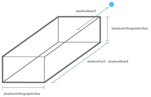
For directional lights, shadows have some additional parameters. Directional lights have no position --- they are ubiquitous -- so in theory they should cast shadows on all objects in the scene. However, doing so would be prohibitively expensive, so Viro requires that we choose a box volume over which the directional light will cast shadows. This box projects out from shadowOrthographicPositionand is of width and length shadowOrthographicSize. It's depth is defined by shadowNearZ and shadowFarZ, as shown in the diagram below.

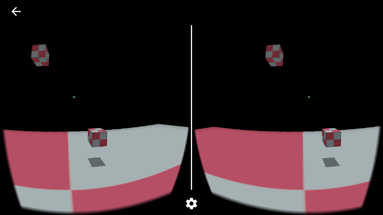
Again, the tighter the shadow region, the higher resolution the shadows will appear. The following example shows a directional light casting shadows over a 10x10 meter area, 5 meters away from the origin in the Z direction.
DirectonalLight light = new DirectionalLight();
light.setColor(Color.WHITE);
light.setDirection(new Vector(0, -1, 0));
light.setShadowOrthographicPosition(new Vector(0, 3, -5));
light.setShadowOrthographicSize(10);
light.setShadowNearZ(2);
light.setShadowFarZ(9);
light.setCastsShadow(true);

Material checkeredMaterial = new Material();
checkeredMaterial.setLightingModel(LightingModel.LAMBERT);
checkeredMaterial.setDiffuseTexture(gridBitmap, Texture.Format.RGBA8, true, true);

Box boxA = new Box(0.5f, 0.5f, 0.5f);
boxA.setPosition(new Vector(-1, 2, -5));
boxA.setMaterials(Arrays.asList(checkeredMaterial));

Box boxB = new Box(0.5f, 0.5f, 0.5f);
boxB.setMaterials(Arrays.asList(checkeredMaterial));

Node boxNode = new Node();
boxNode.setPosition(new Vector(1, -1, -5));
boxNode.setGeometry(boxB);

Quad quad = new Quad(20, 20);
quad.setMaterials(Arrays.asList(checkeredMaterial));

Node quadNode = new Node();
quadNode.setGeometry(quad);
quadNode.setPosition(new Vector(0, -2, -3));
quadNode.setRotation(new Vector((float) -Math.PI / 2.0f, 0, 0));

In the scene depicted above, the DirectionalLight casts shadows onto the horizontal Surface. Note, however, that the DirectionalLight will only cast a shadow for the second Box. The first Box does not cast a shadow because it's not within the shadow region. The shadow region in this example ranges from -5 to 5 on the X axis and 0 to -10 along the Z axis (determined by shadowOrthographicPosition, direction, and shadowOrthographicSize), and +1 to -6 in the Y direction (determined by shadowOrthographicPosition, direction, shadowNearZ, and shadowFarZ). Specifically, the first box is cut off from the shadow region by shadowNearZ.
Note that shadows are:
- Only cast by objects within the shadow region.
- Only rendered on objects within the shadow region.
AR Shadows
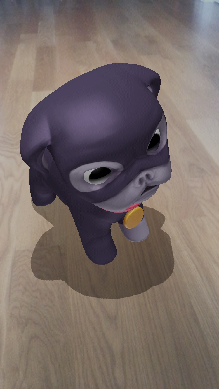
When rendering in augmented reality, it's common to want to render shadows onto real world surfaces. For example, suppose you have a virtual dog resting on a real-world surface, and you wish the dog to cast shadows on the surface. To do this, create a virtual Surface that corresponds to the real-world surface, and set the ShadowMode property on the Surface's Material to Transparent.
Transparent shadow mode enables shadows on the Material, but implements them via the alpha channel. The parts of the surface that are occluded from the light are set to a partially opaque dark grey, and the parts of the surface that in view of the light are made fully transparent. This simulates a shadow over the surface.
For example, the code below creates a Pug with a virtual shadow beneath it.
final ARScene scene = new ARScene();

scene.setListener(new ARScene.Listener() {
    public void onAmbientLightUpdate(float lightIntensity, float colorTemperature) {
    }

    public void onAnchorFound(ARAnchor anchor, ARNode arNode) {
        // Create a Box to sit on every plane we detect
        if (anchor.getType() == ARAnchor.Type.PLANE) {
            DirectonalLight light = new DirectionalLight();
						light.setColor(Color.WHITE);
						light.setDirection(new Vector(0, -1, 0));
						light.setShadowOrthographicPosition(new Vector(0, 4, 0));
						light.setShadowOrthographicSize(10);
				    light.setShadowNearZ(1);
			      light.setShadowFarZ(4);
				    light.setCastsShadow(true);

            Object3D pug = loadPug(...);

            Material material = new Material();
				    material.setLightingModel(LightingModel.LAMBERT);
				    material.setShadowMode(Material.ShadowMode.TRANSPARENT);

	          Quad quad = new Quad(2, 2);
		        quad.setMaterials(Arrays.asList(material));

            Node quadNode = new Node();
          	quadNode.setPosition(new Vector(0, -0.1, 0));
			      quadNode.setRotation(new Vector((float) -Math.PI / 2.0f, 0, 0));
            quadNode.setGeometry(quad);

            arNode.addLight(light);
            arNode.addChildNode(pug);
            arNode.addChildNode(surfaceNode);
        }
    }

    public void onAnchorRemoved(ARAnchor anchor, ARNode arNode) {

    }

    public void onAnchorUpdated(ARAnchor anchor, ARNode arNode) {

    }

    public void onTrackingInitialized() {

    }
});

ViroView view = new ViroViewARCore(context, null);
view.setScene(scene);

Light Influence Bit Masks
Viro supports creating categories of Lights, so that specific Lights can influence specific Nodes. To do this, Lights and Nodes in the Scene can be assigned bit-masks.
During rendering, Viro compares each Light's influenceBitMask with each Node's lightReceivingBitMask and shadowCastingBitMask. The bit-masks are compared using a bitwise AND operation.
If (influenceBitMask & lightReceivingBitMask) != 0, then the Light will illuminate the Node, and the Node will receive shadows cast from objects occluding the Light.
If (influenceBitMask & shadowCastingBitMask) != 0, then the Node will cast shadows from the Light.
This feature can be used to limit the scope of a given Light, or to limit what objects cast shadows for a given Light. In the following example, the first Box will cast shadows and the second will not, and only the first Surface will receive shadows from the Spotlight.
DirectonalLight light = new DirectionalLight();
light.setColor(Color.WHITE);
light.setDirection(new Vector(0, -1, 0));
light.setShadowOrthographicPosition(new Vector(0, 8, -5));
light.setShadowOrthographicSize(10);
light.setShadowNearZ(2);
light.setShadowFarZ(9);
light.setCastsShadow(true);
light.setInfluenceBitMask(2);

Material material = new Material();
material.setLightingModel(LightingModel.LAMBERT);
material.setDiffuseTexture(new Texture(gridBitmap, Texture.Format.RGBA8, true, true));

Box boxA = new Box(0.5f, 0.5f, 0.5f);
boxA.setMaterials(Arrays.asList(material));

Node boxNodeA = new Node();
boxNodeA.setGeometry(boxA);
boxNodeA.setPosition(new Vector(-1, 2, -5));
boxNodeA.setShadowCastingBitMask(2);

Box boxB = new Box(0.5f, 0.5f, 0.5f);
boxB.setMaterials(Arrays.asList(material));

Node boxNodeB = new Node();
boxNodeB.setGeometry(boxB);
boxNodeB.setPosition(new Vector(1, -1, -5));


quad quadA = new Quad(2, 2);
quadA.setMaterials(Arrays.asList(material));

Node quadNodeA = new Node();
quadNodeA.setGeometry(quadA);
quadNodeA.setPosition(new Vector(0, -2, -3));
quadNodeA.setRotation(new Vector((float) -Math.PI / 2.0f, 0, 0));
quadNodeA.setLightReceivingBitMask(2);


Quad quadB = new Quad(2, 2);
quadB.setMaterials(Arrays.asList(material));

Node quadNodeB = new Node();
quadNodeB.setGeometry(quadA);
quadNodeB.setPosition(new Vector(2, -2, -3));
quadNodeB.setRotation(new Vector((float) -Math.PI / 2.0f, 0, 0));
The default mask is 0x1.
Bloom
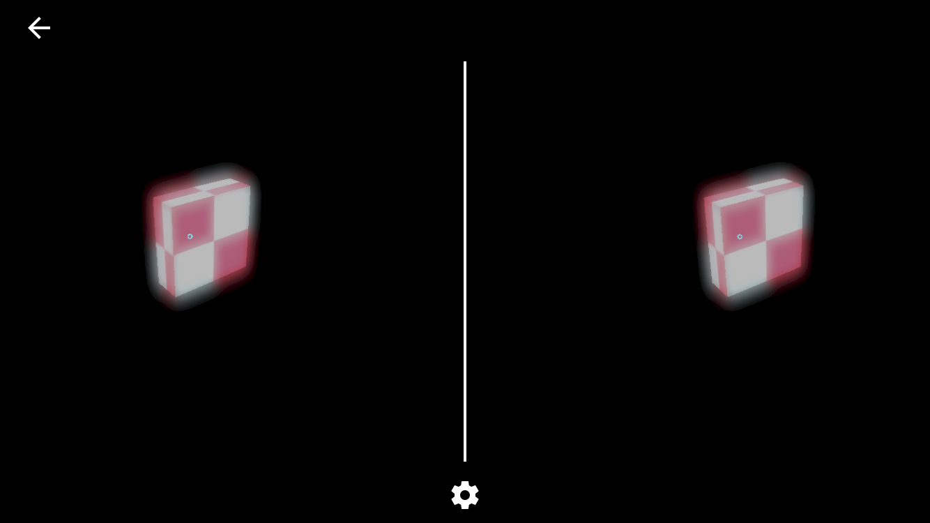
Bloom is an effect used to simulate extremely bright light overwhelming a camera capturing a scene. It's often also referred to as "glow". Because Viro supports High Dynamic Range (HDR) rendering, you can integrate bloom into your scenes.
To do this, set the bloomThreshold of the Material you would like to glow. This value specifies at what 'brightness' the pixels of the surfaces using this Material should start to bloom. Brightness is effectively the magnitude of the final color of a pixel (modified for the human eye: specifically, it is the dot product of the final color with (0.2126, 0.7152, 0.0722)).
For example, if bloomThreshold is set to 0.0, then all surfaces using the Material will bloom. If bloomThreshold is set to 1.0, then only those pixels of the surface whose brightness exceeds 1.0 (after lights are applied) will bloom.
The following example creates a glow on the box by using a bloomThreshold of 0.5 and a combination of lights that exceeds 0.5 brightness on the box's surfaces.
Scene scene = new Scene();

Spotlight spotlight = new Spotlight();
spotlight.setPosition(new Vector(0, -0.25f, 0));
spotlight.setDirection(new Vector(0, 0, -1));
spotlight.setAttenuationStartDistance(5);
spotlight.setAttenuationEndDistance(10);
spotlight.setInnerAngle(5);
spotlight.setOuterAngle(20);
spotlight.setColor(Color.WHITE);
spotlight.setIntensity(1000);

AmbientLight ambient = new AmbientLight();
ambient.setColor(Color.WHITE);
ambient.setIntensity(1000);

Node lightNode = new Node();
lightNode.addLight(spotlight);
lightNode.addLight(ambient);

Geometry box = new Box(2, 2, 2);
Material boxMaterial = new Material();
boxMaterial.setDiffuseTexture(new Texture(gridBitmap, Texture.Format.RGBA8, true, true));
boxMaterial.setBloomThreshold(0.5f);
boxMaterial.setLightingModel(LightingModel.LAMBERT);
box.setMaterials(Arrays.asList(boxMaterial));

Node boxNode = new Node();
boxNode.setGeometry(box);

scene.getRootNode().addChildNode(lightNode);
scene.getRootNode().addChildNode(boxNode);

Updated about 4 years ago